Important: The information presented here is for the use of a qualified, experienced technician. Without the background knowledge which comes with training, you risk doing more damage then good to the copier & also risk your own safety. If you are not willing to take 100% responsibility for your actions, do not use the information posted here. Thank you. Read our conditions of Use for more information.
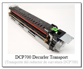
DCP700 / J75 Family, V80 style - Decurler Transport Repair Instructions
DCP700/J75 or V80 style - Decurler Transport Rebuild Instructions
| Technical Specifications |
|---|
Rebuilding the Decurler Transports… Xerox® Digital Color Press® DCP-700/700i/770, Color Press C75/J75 & also Versant® V80, V180, V2100, V3100
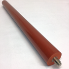
It’s finally becoming possible to rebuild or repair the Decurler Transport Assemblies. Foam Decurler Rollers are spared in the J75 parts book, where they were missing from the DCP700 list. We’ll check-out a good way to protect the gears on the front end of the unit. These four little white gears have become famous for getting all chewed up, for reasons we’ll discuss. Then we’ll also look at taking one of these units apart far enough to replace these four gears.
There are 3 versions of the Decurler Transport Assemblies. Each version has its own OEM part numbers. They are very similar, although there are some differences between them too. The large Foam Rollers are the same for all three versions.
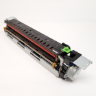
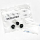
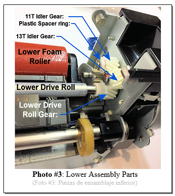
In many cases the limiting factor for these units turns out to be four little white gears at the front end. There are two Idler Gears (one with 11 teeth, and one with 13 teeth), and there are two Drive Gears which fit onto ‘D’ shafts (one fits on the Upper Drive Roll and one fits the Lower Drive Roll). These little white gears are in harms way of toner and developer falling-down from the Developer Unit above. The grit gets into the teeth of the gears and wears them down rather quickly. One look at the ramp-like black front-end cover makes it clear why so much grit lands on the gears. A mylar sheet installed on this cover will serve as a protective cover for these gears. (see Photos #1 and 2)
Now let’s open one of these up and see how to get to the 4 important gears.
TOOLS REQUIRED:
PARTS WHICH YOU MAY NEED:
PROCEDURE - Part 1:
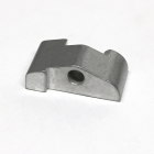
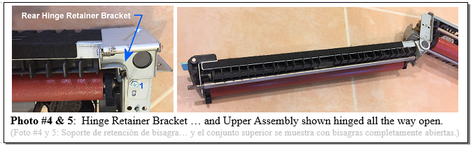
1. Lay the unit on its right side and remove the Hinge-Limit Bracket (1 screw) (see Photo #4). While holding both upper and lower halves steady, carefully lift the green latch to release the two halves and open the unit up all the way.
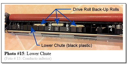
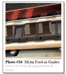
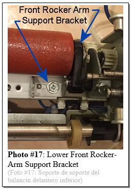
9. Remove the Upper Decurler Drive Roll. At the rear end, remove 1 e-clip and the bearing. At the front end, its best to leave the black plastic retainer in-place, as it is easily broken if you try to remove it (see Photo #11). Pop the front e-clip and bearing off and the Upper Decurler Drive Roll comes right out. Inspect the Drive Roll’s surfaces for any serious wear. If the roller’s surface has developed a wide groove where the pinch roll makes contact, it could potentially cause wrinkled copies. 10. With the Drive Roll off, the Drive Back-Up Roll and its narrow metal shaft will drop off easily. Inspect and clean the single white Back-Up Roll and its tiny bearings. (see Photo #12) 13. Remove the Upper Decurler Foam Roll (named the Pene Roll in the OEM parts book). Pop off the front and rear e-clips and slide the bearings off. Inspect the Rocker Arms which support the Foam Roll for damage. You can leave the Rear Rocker-Arm, and its bracket, in place. 15. Inspect the 12 mylar Feed-in Guides on the Lower Chute for signs of damage or burrs (see Photo #16). Repair or replace them if necessary. Also clean up and inspect the three Drive Roll Back-Up Rolls. Make sure the tiny bearings spin freely and remain seated firmly in the ends of the rolls. Note that these 3 are identical to the single one in the upper half). Well that should do the trick! May your decurlers keep your copies nice and flat and beautiful. Happy repairs everyone!
|
| Information Reference |
Author: Britt Horvat This is one of our own Partsdrop Write-ups. We hope you find it helpful! |


Related Products