Important: The information presented here is for the use of a qualified, experienced technician. Without the background knowledge which comes with training, you risk doing more damage then good to the copier & also risk your own safety. If you are not willing to take 100% responsibility for your actions, do not use the information posted here. Thank you. Read our conditions of Use for more information.
D95 / 4112 / 4110 Family Drum Cartridge Rebuilding
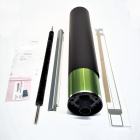
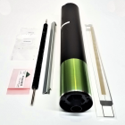
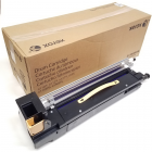
Xerox® 4110 style Drum Cartridges … Recondition / Recycle the Drum Cartridges for the WorkCentre® 4110 / 4112 / 4127 / 4590 / 4595 (013R00646) & D95 / D110 / D125 / D136 (013R00668)
| Technical Specifications |
|---|
The first group of models: 4110, 4112, 4127, 4590, 4595, all share the same drum cartridge although over time there have been MANY part numbers. The most current part number for the “4110 version” of the cartridge is 13R646 (or 013R00646). Other part numbers include: 13R635, 13R639, 13R653, 13R610, 13R640. It remains unclear which cartridges are for which markets among these part numbers. If there are different versions, the main difference between ctg reorder numbers is mostly just the difference between the chips, or “CRUMs” (Customer Replaceable Unit Monitors) which are found on the cartridges. These CRUMs also keep track of the copy count and need to be replaced to reset the drum count for the machine. From reports in the field, most machines (if not all) will accept the 13R646. Another difference among these, is that some, but not all of the cartridges, have an “anti-tamper” plate in front of their release latches. The Anti-tamper plate is designed to keep a customer from removing the cartridge without the use of a screwdriver.
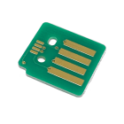
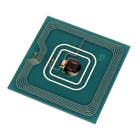
The more recent D95 family of models use a drum cartridge which is extremely similar to the 4110 version. It comes apart the same way and uses the same drum, and other components, however it also has some substantial changes from the 4110 version. This new cartridge we’ll call the “D95 version”. It is found in the machine models: D95, D110, D125 & D136. These started out using part number 13R666 (013R00666) which later was replaced by 13R668 (013R00668). The first difference is the location of the CRUM chip. The 4110 version used an RF (Radio Frequency) type of chip which can be found hiding underneath the rear end of the top cover of the drum cartridge. It doesn’t make any physical contact in the machine. The D95 version now uses a physical contact type of chip which is exposed and mounted on the top of the Front End Cover. The other immediately noticeable difference is that the 4110 version has a Pre-Transfer Corona along the bottom left side of the cartridge, while the D95 version is missing the Pre-Transfer Corona entirely.
PROCEDURE Note that most of the screws are #1 philips head / 5.5mm hex driver. A few have fine metal thread… keep track of those few so they go back in the same places where the belong as they are responsible for making ground contacts in some cases.
1.) Remove the Top Cover (4 screws) For the 4110 version of these cartridges, you will find the RF (Radio Frequency) CRUM chip which is hiding under this cover near the rear end of the cartridge (see Photo #1). If you’re working on the D95 version of the cartridge, the CRUM will instead be found on the top of the Front End Cover. 2.) If there is a black plastic plate in front of the yellow release handle, remove it (1 screw)… this is an anti-tamper plate designed to make the cartridge less tempting for the customers to remove from the machine. It makes it necessary to have a screwdriver in hand, so it makes the customer think twice, which is a good thing since they are then less likely to damage the drum or accidentally expose the drum to excessive light.
3.) Remove the Front End Cover (2 screws from the front end)
4.) Take off the Drum Picker Finger Assembly (2 screws), and the metal plate on the bottom left side of the cartridge (2 screws). This plate sits just below the Pre-Transfer Corona (see Photo #2) *NOTE that the D95 version of the cartridge is missing the Pre-Transfer Corona, although the metal plate is still there)
5.) Next Remove the lower right corner cover (held by 2 clips) (see Photo #3).
6.) Then the Pre-Transfer Corona Assembly comes off by removing 1 screw from the front end (see Photo #4) and then you can shift the corona assembly towards the front end of the cartridge to remove it… CAUTION: This particular screw has a fine machine-threading… don’t mix it up with the coarser plastic-thread screws because this one makes a vital ground contact)
7.) Similarly the Pre-Charge Corona Assembly comes off by removing 1 screw from the rear end and then shifting the assembly toward the rear to remove it. (see Photo #5).
8.) Restring the Corona Wires on the Pre-Transfer and Pre-Charge Corona Assemblies (these two wires are shorter than the ones in the Charge Corona Assembly). Be gentle and patient here so as not to break the new Corona Wires (4110PCW)
9.) Next comes the Charge Corona Assembly which is held on by 1 screw from the rear end (see Photo #6). Rebuilding the Charge Corotron is an important part of getting good life out of a rebuilt cartridge. You will replace the Charge Grid and the 2 Charge Corona Wires. Wear surgical gloves when handling the new Corona Wires and Grid to avoid oils from your fingers getting on these components because fingerprints can cause copy quality issues.
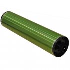
10.) Now for the Drum itself (4110DR). Turn the cartridge on its right side so that the drum is facing upwards. Remove the 3 screws from the Rear Drum Hub (refer back to Photo #5), and 3 screws from the Front Drum Hub (refer back to Photo #4) (CAUTION: these 6 are the fine metal-thread types of screws, don’t get them mixed up with the coarse plastic-thread screws) . Then while holding onto the drum, extract the front and then the rear drum hubs and lift the drum out of its cradle. (see Photo #10) When reassembling use a small dab of plastislip grease or similar light lubricant grease in the drum hubs, since they serve as the bearings for the drum. When installing a new drum, keep it shielded from light as long as possible during the reassembly procedure to prevent the possibility of “light-shock” damage to the drum.
11.) Replace the Drum Cleaning Blade – 4110DB (2 screws).
12.) Vacuum the Cleaning Brush and the cavity behind it, taking care not to damage the mylar Recovery Blade. If the Recovery Blade (4110RB) gets damaged or is coming unglued, replace it with a fresh peel-and-stick Recovery Blade. First make sure you clean off the old one and any adhesive thoroughly.
13.) For a thorough cleaning, remove the Cleaning Auger Cover (3 screws). Be very careful with the foam gasket on this cover (see Photo #11), as removing the cover will disturb this gasket. You’ll need to be gentle and do as little damage to the foam gasket as possible… so that it’ll keep doing its job when you’re done. With the Cleaning section top cover off, you will get better access to the cleaning auger which moves the waste toner away from behind the cleaning blade to exit the cartridge through the sliding shutter at the rear end. Be gentle, but clean out as much of the waste toner as possible using a vacuum. Keep an eye out for any broken or worn out parts, such as the waste auger, the gears which drive it, or the shutter mechanism at the rear of the auger.
14.) Reassemble it all! Be sure to use starting powder so that the blade doesn’t stick to the drum, and rotate the drum a few times by hand to make sure it starts right. If you want to use toner as your starting powder, you need to keep some of the toner from behind the cleaning blade for this purpose. Do not use toner from the waste bottle, nor from a toner cartridge, because both have gritty developer material mixed in. Also pay attention to where the metal-thread screws belong (the 3 each for the front and rear drum hubs, & 1 more attaches the Pre-Transfer Corona Assembly). Congrats! You’ve got it licked ! |
| Information Reference |
Originally published as an article in ENX Magazine, written by Britt Horvat of The Parts Drop. |


Related Products