Repairing and rebuilding the Print Cartridges for the WC-5945/5955 and, also the new B8045/B8055/B8065/B8075 & B8090

The new AltaLink B8090 family of machines use an extremely similar Drum / Developer Cartrides as their predecessor models; WC-5945/5955, only with a different CRUM chip. We did cover the rebuild procedure of the upper half of the 5945 cartridges back in June of 2015. Now let’s revisit these since the same procedure will work on the new B8090 cartridges. We’ll also go a little deeper and cover the developer material replacement end of things.
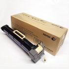
The WC-5945/5955 Print Cartridge is sold under the part number 013R00669 (13R669). It has a stated yield of 200K according to the machine’s brochure. Now there is a new Family of models in the style which uses an extremely similar cartridge (same drum, blade, etc but a different CRUM chip). The AltaLink B8090 / B8075 / B8065 / B8055 / B8045 use 013R00675.
These cartridges have an upper half which has the Drum, Blade, Charge Roll and a Cleaning Roll (a white foam roll). The lower half has a developer station including an ATC Sensor (Automatic Toner Concentration).
Now let’s get into the procedure of separating the upper drum / cleaning half and the developer station. This can get pretty messy, so make sure you are working over a drop-cloth. One notable change from the previous version of this article… It turns out it is easier to handle the drum without it falling over and getting hurt if you turn the whole unit upside down before removing the white Drum / Mag Roll Bushings.
You’ll need a Torx T-10 Safety driver bit (T10S):
PROCEDURE:
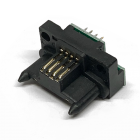
1. Replace the CRUM chip from behind the right side of the front-end cover (1 screw – Torx T-10). (see Photo #1)
(CRUM chip part#’s: B8090CN or 5945CN)

2. Next remove the Rear End Cover (2 screws & release one clip on your lower left) (see Photo #2). Take care from here-on that the white Drum / Mag Roll Bushing does not slip out until you’re ready, or else the drum becomes loose and can be easily damaged. Also watch over the Cleaning Auger Coupling as it will “pop” off the auger as you remove the cover. Keep the small white coupling handy as you’ll need it for turning the mag roll later on.

3. Next comes the Front End Cover (2 screws) (see Photo #3).

4. Then take off the Front Inner Plate (3 screws, T-10) (see Photo #4)… be very careful that both the front and rear white plastic Drum / Mag Roll Bushings stay in place.

5. Now very gently turn the unit upside down. Extract the white Rear Drum / Mag Roll Bushing.
6. Next go to the front end. You will need to hold up the front end of the Developer Station as you extract the Front Drum / Mag Roll Bushing. Caution: there is a metal contact with a ‘D’ shaped hole which fits over the front ‘D’ shaft of the mag roller. This ‘D’ shaft must not be allowed to rotate, as it is designed to be fixed in place by the contact. This piece determines the angle of the magnet inside the Mag Roller and must not change position (See Photo #5). You will want to remove the contact from the ‘D’ shaft only for a moment… slide the Drum / Mag Roll Bushing off and then immediately put the contact back on the ‘D’ shaft. The Developer Station can now be lifted off.

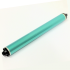
7. The Drum with its bearings can now be lifted out of its cradle. This exposes the Charge Roll & Drum Blade (see Photo #6)

8. The Charge Roll can now be replaced (use a little bit of conductive grease on the plastic cradles which the charge roller sits in). The white foam roll just behind the Charge Roll is the Charge Roll Cleaning Roll. It comes out easily at this point as well.
9. Finally, you can remove the Drum Cleaning Blade (2 screws) and gently vacuum out the waste toner auger behind the blade (be very careful not to hurt the mylar recovery blade)
.
Now let’s continue where we left off in the June 2015 article. We will open the Developer half of the cartridge and replace the developer material.
10. Prepare to remove the Developer Station’s Top Cover. There are two screws from the side of the unit (one at front and one at the rear end) (see Photo #7). There are also two springs to release from the Toner Dispense Shutter. Then there are 3 Clips (two shown in Photo #7, one in Photo #8).


11. Release the Metal contact at the front end of the DV Station from the Top Cover (continue to keep the ‘D’ shaft retained by this contact piece). Now you can lift the front end of the Top Cover, pivoting it up so that it hinges at the rear, until its two indexing pins comes out of the holes where they are seated. When it comes off, watch that you don’t lose the small black plastic anchor / spring support as it will now fall right off. (see Photo #9).

12. Next you’ll be dumping the old Developer out of the unit. There are three things you must pay close attention to:
Keep the Mag Roll’s Keyed Bushing in-position at all times. (see Photo #10)
You can use the white Mag Roll Drive Coupling but be careful not to lose it.
Continue to keep the metal contact at the front end on the ‘D’ shaft of the Magnet, and also on its plastic retaining pin.
With those three things in mind, tilt the DV Unit vertically so the rear end points downward over an appropriate waste container… Dump what will fall out. Then turn the Mag Roll and brush it off with a soft bristled bottle brush or paint brush to clear the surface of the Mag Roll. Turn the Mag Roll about ¼ turn and brush it off again… you will need to do this about 40 times before you see less and less of the mag roll being covered with developer material. Eventually it will all be brushed out. This part can be time consuming. Be patient. You should not use a vacuum to clean the unit out for two reasons. First the ATC Sensor (Automatic Toner Concentration Sensor) is static sensitive and a vacuum could blow the sensor. Second, there are some tiny parts which could get sucked out easily. In particular, there is small rectangular shaped screen piece with a narrow cover over it near the rear end of the unit. This piece is located in the “wall” between the augers of the developer mixing area. Be careful not to lose those or accidentally dislodge them with the brush. (See Photo #11)


13. Once all the old Developer has been dumped and brushed out, you can fill the top cover with new developer and install a peel-and-stick Developer Pull Seal to keep it all up in there until the customer pulls the seal at the time of installation.
14. Reassemble it all with care.
That’s it! You’ve got it licked! I hope you all enjoyed the article. Have a great month!
|