Important: The information presented here is for the use of a qualified, experienced technician. Without the background knowledge which comes with training, you risk doing more damage then good to the copier & also risk your own safety. If you are not willing to take 100% responsibility for your actions, do not use the information posted here. Thank you. Read our conditions of Use for more information.
WC-4150 Fuser Module Rebuild Instructions
Rebuild the fusers for the WC-4150
| Technical Specifications |
|---|
For Xerox® models: (WorkCentre) 4150, 4150s, 4150x, 4150xf
With financial times getting a little bit tighter out there, our industry will likely see more folks going back to fixing stuff instead of simply replacing it. The repair end of this wonderful industry has long been known to be relatively recession-proof. When times are good, machines sell. When times are not as good, machines get repaired more often than not. Fuser Modules for the Xerox brand office machines represent a great example of an opportunity to save your customer some bread while making more money for yourself than you would if you only sold new fusers. With the machines getting to be so modular, the fuser is a no-brainer to replace… but then what… do you throw out the core or fix it up for the next customer? Here is a machine which I think you will agree is worth learning about. The WorkCentre 4150 is just beginning to come off of manufacturer warranty and the fusers are going to need replacing (or repairing if you will). Parts are available and the fuser is pretty easy to take apart as we’ll see in this article. We’ll start with an overview and get into the procedure of taking one apart. Then we’ll wrap up with some information about the Status Codes relating to the fuser, learn how to troubleshoot those codes and nail down how to reset the fuser’s counter.
The WorkCentre 4150, 4150s, 4150x, & 4150xf machines all use a fuser sold as a complete unit under the part number 002N02557 which retails for around $310.-.
The parts in this particular fuser are actually spared (a rare occasion for Xerox these days and worthy of applause!). The Heat Roller / Heat Element assembly and the Pressure Roller are spared, as are most of the other pieces of any real importance; thermistor assembly, thermal fuse assembly, Picker Fingers, Bearings, Bushings, Idler Gear, etc…
Another nice thing about this type of fuser is that there are no sneaky kill chips or identifying / indexing resistors to worry about (at least none that I was able to detect or find reference to). The fuser counter can be reset from the diagnostics although the machine will continue running even if the fuser is over its threshold, only stopping if a problem is detected with the fuser’s performance.
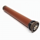
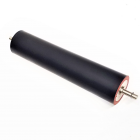
The machine itself will remind you at first glance of the M20 / 4118 model machines but it’s much beefier and runs 45 pages per minute. The fuser likewise is built for the extra speed and volume. Like the M20, this one does not use a traditional Heat Lamp, but instead employs a Heat Element which is built right into the Heat Roller Assembly (if you ever dissect one, you’ll find a wire element inside there which looks like something out of an old toaster-oven. That part also includes the Fuser Drive Gear and one of the two Heat Roll Bushings or Sleeves when you buy it. The Pressure Roll is a relatively large diameter Teflon sleeve type of roller.
The fuser comes apart rather easily although there are a few possible tricks and potential trouble-spots to be aware of. Lets get right into it shall we?
Fuser Disassembly Procedure: First let’s get on the same page as one another as far as orientation. The “top” of the unit is the part which has an opening to the Heat Roller where you can see the Picker Fingers. The “outside face” is the ribbed cover which is facing out at you when you open the door on the machine to get to the fuser module (See Photo #1) (the inside face then faces into the machine when the fuser is in place - it has the thermal fuses and thermistors and the fuser connector). Then the “rear end” is the geared end of the fuser and the “front end” is, well… the other end.
1. Start by releasing pressure by removing the two pressure springs (one front and one rear on the top of the assembly). Then remove two screws from the ‘inside face’ (one near the top on the front end (see Photo #2) and the other is near the top close to the rear, geared end).
2. Gently separate the two halves of the fuser which hinge on each other at the bottom. (See Photo #3)
3. Concentrate next on the Heat Roll half. Remove both the front and rear “Carbon Brushes” (spring-loaded metal studs which make contact with the metal plates at either end of the heat roller assembly). These provide the AC voltage for the element inside the heat roll). The Carbon Brush assemblies are each held on by 3 screws. (See Photo #4 )
4. Be very careful with the 4 Picker Fingers as you now remove the Heat Roll Assembly from its cradle (the fingers can potentially get damaged, and they would scratch the Heat Roll’s surface rather easily if you were not paying close attention to them). The Heat Roller Assembly lifts right on out now, along with its Bearings and Bushings (the bearings and bushings are easily removed from the roller at this point). Now you can see the inside faces of the Thermistors (2) and Thermostats (2 joined in an assembly). (See Photo #5)
5. Next you can take off the Fuser Input Guide (3 screws). Don’t lose the little static elimination brush (it contacts the Pressure Roll). It is trapped under the Fuser Input Guide near the rear end and will fall right off once the guide is removed. Also take off the Front Jam Lever and it’s spring (1 screw from the front) (See Photo #6)
6. Release the front Press Roll Bracket and slide off the front bearing. Then the Pressure Roller can be lifted out and the rear Bearing will slide right off as well. Under the Pressure Roller is a metal Cleaning Roll which is just sitting in a pair of spring loaded cradle-like line-bearings (remove it because it is loose and will fall out easily).
7. During reassembly, there are a couple of important things to know. First of all… when you reinstall the Heat Roller, to avoid damaging the roller, you need to pull back all 4 picker fingers at the same time (I found using a pen or pencil worked just fine. It enable me to pull back the fingers with one hand while I lowered the Heat Roll Assembly into place using my other hand). Another thing to pay attention to is that when you install the Heat Roll Bushings (sleeves) on the Heat Roll, there are two scallop shaped holes in the Heat Roll which need to line up with the scallop shaped protrusions on the inside of the bushing. Finally, make sure that the springs on the Jam Release Levers are positioned against their corresponding slots on the fuser frame.
That should do the trick! Now to reset the Counter….
Resetting the Fuser’s HFSI Counter: Resetting the HFSI Counter (High Frequency Service Item Counter) is done by first entering Diagnostic Mode (hold down the ‘#’ key and then press the’ Access’ key… the Diagnostic Login Window will show up. Enter the password (the default is ‘1934’) and touch ‘enter’ (note that if you put in the wrong password 3 times, the machine will lock-up for 3 minutes before you can try again). Now touch the ‘HFSI’ tab to bring up the HFSI Table. Look for & select the Fuser. Its status will show either “off” (not being tracked) or “OK” if it is not over the count yet, or it’ll say “Check” if it is over its count. To reset the fuser’s actual count to zero, select and hightlight the fuser on the list and then touch ‘Reset’ followed by ‘OK’. Now choose ‘Exit’. Touch ‘Call Closeout’. From this screen leave “Reboot Copier” set to “yes” so that your HFSI Fuser counter will be properly reset during the rebooting process.
Fuser related Fault Codes (10-100,. 10-200, 10-300):: The codes which point to fuser problems all start with 10… 10-100, 10-200 indicate a fuser error where the fuser was “under-temperature”. Fault Code 10-300 means an overheat was detected, and 10-400 is listed as a “Fuser Unit Error”. If you want to check beyond the fuser itself, it’ll be helpful to you to know where the wiring goes and which connectors are important to these Fault Codes. The main Connector on the fuser itself has 2 larger flat pins which are as you may guess the contacts for the Heat Element circuit (the circuit also includes both of the Thermostats or thermal fuses). The 4 smaller flat pins in the same connector go to the 2 thermistors. If you follow the wires from the fuser connector’s socket in the machine, it’ll lead you to the “Power Supply Unit 2” at the following connectors: CON3, CON8, & CON9. The signal comes in at CON4 on Power Supply Unit 2… the signal is given from the Main Board and the connector is CN7.
That is it for this month. We’ll have to revisit this model in the upcoming months to see what sort of fault codes these machines will be throwing at you. We’ll also turn our attention on the diagnostics to see what memory adjustments and component tests are available.
|
| Information Reference |
Author: Britt Horvat, with special thanks to Kurt for his expertise and thanks also for support from whole Partsdrop gang. Originally published as an Article in the marvelous ENX Magazine - www.enxmag.com :) All rights reserved... you can distribute copies as long as you include a link to the source website: www.partsdrop.com |


Related Products