Important: The information presented here is for the use of a qualified, experienced technician. Without the background knowledge which comes with training, you risk doing more damage then good to the copier & also risk your own safety. If you are not willing to take 100% responsibility for your actions, do not use the information posted here. Thank you. Read our conditions of Use for more information.


WC-5945 & B8090 Family - Fuser Module Rebuild Instructions

Rebuild the fusers for the WC-5945, 5955

Technical Specifications

For Xerox® models: (WorkCentre) WC-5945, 5955, & (AltaLink) B8090, B8075, B8065, B8055, B8045


5945 Fuser Rebuild Header


            Last month we took a peek at the Drum Cartridges (imaging units) for the brand new WorkCentre 5945 style.  I like the looks of these new models so I was curious about the consumables.  Now let’s have a shot at the Fuser Modules.


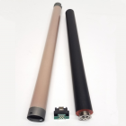
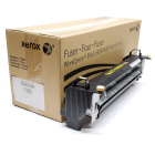
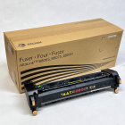
           The WC-5945 / 5955 Fuser Modules are sold under the part number 109R00847 in the U.S. (110 Volts) or 109R00848 in European markets (220 Volts).  According to the brochure, this fuser is rated for a stated yield of 250K.  The lower speed models in the series (B8045 / B8055) use the same fuser (same part# as the 5945 as mentioned above).  The higher speed models use a different part number:  109R00850 (110 volts) or 109R00851 in European markets (220 volts). 

  . 

I have to admit I was originally lured into taking a closer look at this fuser because from the outside, many of the parts “looked” familiar.  I hoped I would find that some of the parts were already available. Well, looks can be deceiving.  Very few parts in this fuser are available as of yet…although I’m certain this will change with time. The Heat Roll looked familiar at first glance, but it is not like any earlier heat rolls we have seen.  Also the picker fingers looked like those found in a much older model (think circa 1990 with the analog copier models 1012, 5011, 5012, & 5014)… but again they did not prove to be the same, in spite of being the same basic design idea.  The one thing which was very nice is that the CRUM chip is already available (5945FCN).  So the fuser count can be reset easily by replacing just the CRUM chip.  This CRUM chip is easy to get to too… mounted right on the outside of the fuser with one screw. 


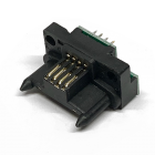
Let’s get right into the procedure starting with the location of the Fuser CRUM chip (Customer Replaceable Unit Monitor).  It can be found mounted to the “Inner Face” of the fuser by one screw… piece of cake.  This piece tells the machine which version of fuser it is (110 volt vs. 220 volt) and the machine “counts” on the CRUM chip… keeping track of the copy count which the fuser has used so far.


PROCEDURE:
1. First remove the Inner Cover (3 screws – 5.5mm nut driver or #1 phillips head) (see Photo #1)… this gives you access to the 2 Fuser Thermostats and the Thermistors. 


5945 Fuser Rebuild Photo #1

 
2. Replace the Fuser CRUM chip (1 screw), which is mounted on the “inner Cover” which you just took off. 

  
3. Next remove the Outer Cover (the piece with which faces you when you see the fuser in the machine… it has the two handles and the two thumbscrews on it.  It is held on by 2 screws from the outer face… one near the front end and the other near the rear end.

 
4. Now you’ll go after the Exit Baffle which is just opposite of the picker fingers.  Start by taking off the plastic cover on that baffle(4 screws… see Photo #2).  


5945 Fuser Rebuild Photo #2


5. The Exit Baffle has a pair of pull springs (one at either end) which work to keep the baffle closed.  Use a spring hook to release the springs (first take note where they hook in because it’s not that obvious later… see photo #’s 3 & 4). Once the springs are off, you can pivot the baffle away from the heat roll and the picker fingers.  You’ll want to pay attention from this point on… taking care not to allow this metal baffle to flip back against the heat roll as it could cause damage.


5945 Fuser Rebuild Photo #3-4

 
6. The Picker Finger Assembly can now be removed (4 screws… see Photo #5)


5945 Fuser Rebuild Photo #5

 
7. Next take off the “Outer Frame” which is a metal frame piece held by 2 screws from the front end and 2 screws from the rear end.  (Refer to Photo #6 which shows the front end)


5945 Fuser Rebuild Photo #6

 
8. Disconnect the Heat Lamp’s spade lug connector from front Thermostat (see Photo #7)


5945 Fuser Rebuild Photo #7

 
9. Take note of the positions of the front and rear Pressure Tower Screws… Mark them if you need to, so you can return them to the same positions when you reassemble the fuser later.  You’ll want to end up with even pressure from end to end.  Back out each of the Pressure Tower Screws half way first, then continue to back each out the rest of the way till they’re all the way out.

 
10. With the Pressure Tower Screws released, the Pressure Roller’s holder arms can pivot open till you can lift the Pressure Roll out of its cradle (see Photo #8).  Before you remove it, take note how the Outer Exit Baffle frame pivots on the two Press Roll Bearings. The Press Roll Bearings have their flanges positioned outside of the press roll frame’s cradles and they’re held onto the Press Roll’s shaft by a pair of e-clips.


5945 Fuser Rebuild Photo #8

 
11. The two Thermistors need your careful attention.  They are fragile.  The Thermistor Heads are metal coated with a very thin layer of Teflon or a similar material…(see Photo #9) they are like the ones in the C123 fuser modules which were known to wear out shortly into the second cycle.  The recommendation is to put one layer of Thermistor Tape (Kapton tape) around them, fixed in place so the tape can not fall off.  This tape will protect the surface of the Thermistor Head and add longevity to your repaired fuser module.  It is important that the tape is only one layer thick at the contact point and that it can not buckle the head away from where it makes contact with the heat roll’s surface.


5945 Fuser Rebuild Photo #9

 
12. Next you’ll be gunning for the Fuser Heat Roller.  Remove the Front Lamp Holder Bracket (1 screw… refer back to Photo #6), and loosen the Rear Lamp Holder Bracket by removing the one accessible screw (refer back to Photo #8)… Note that the rear Lamp Holder Bracket also has the Main Fuser Connector attached to it and there is a second screw tucked in behind the wires which you need not remove. You only need a little wiggle room, so you can sneak the bulky Heat Roll Gear out of the frame in the next step.

 
13. Now gently raise the Heat Roller’s front bearing out of its frame, followed by the rear bearing.  Slide the Fuser Heat Roll out over the Heat Lamps and their wires.  (note about the Fuser Heat Lamps: the Hi-watt lamp is 115V / 825W with a white wire, and the Low-Watt lamp is 115V & 655W with a red wire).

 
14. Reassemble the fuser being careful in particular with the Thermistor heads and the Pressure Tower Screws positions like we talked about earlier.  
 

Nicely done!  


Information Reference

Author: Britt Horvat, with special thanks to Kurt for his expertise and thanks also for support from whole Partsdrop gang. Originally published as an Article in the marvelous ENX Magazine - www.enxmag.com :)

All rights reserved... you can distribute copies as long as you include a link to the source website:  www.partsdrop.com