Xerox® 7556/7855 Family - Repairing & Rebuilding the Fuser Modules
for WorkCentre® 7525, 7530, 7535, 7830, 7835 & WC-7545, 7556, 7845, 7855, Also Phaser® 7800

The WC-75xx and WC-78xx family fuser modules are pretty serious pieces of equipment. With some excellent parts now available, it’s time to take these apart and figure out the best way to go about replacing the Fuser Heat Belt, Slip Sheet and Pressure Roller, and the Fuser Reset Fuse. You will find this one is relatively time consuming to rebuild, but with the new fusers retailing for over $700.-, they are well worth your time. This one is not for the faint of heart. It requires a technician of high mechanical skills to rebuild one of these successfully. Even a talented tech should allow themselves a good 2 hours to rebuild one for the first time.
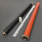
These things are well built except for a problem with insuficcient lubricant inside the heat belt which we'll get into. They have a stated yield of 360K pages. They are not typical of other Xerox fusers we’ve covered. For one thing they use a flexible “Heat Belt” rather than a rigid heat roll like most fusers. Then for the heating they don’t use traditional fuser lamps. Instead these use a newer technology known as induction heating which reduces the amount of energy required to keep it hot. The heat on the heat belt’s surface is produced by a piece which is adjacent to the heat belt (not inside of it, as one might expect). Inside the Heat Belt you’ll instead find a Thermal Control Assembly which has the thermistors and thermostats mounted to it. The pressure is done by a more traditional looking Pressure Roller (rather than a pressure sleeve as we’ve seen in recent models).
Inside the Heat Belt there is a piece of fabric-like material called the “Heat Belt Slip Sheet” which lines up inside the heat belt opposing the pressure roller’s nip. It is designed to allow the heat belt to slip across it as it rotates. The Slip Sheet needs to have adequate lubrication to function properly (Fuser Heat Belt Oil). The drying up of the oil on the Slip Sheet is responsible for a majority of the fuser failures. What happens is the Slip Sheet dries up and the friction increases until eventually the fabric tears off of its mounting tabs and bunches up inside the heat belt. Eventually the heat belt will be deformed or it will tear. It is absolutely critical to apply plenty of Heat Belt Oil to the Slip Sheet (both sides… and work it in so it fills all the voids in the fabric), this way your rebuilt fuser will go the full cycle.
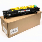
There are two very similar versions which both come apart the same way. There is a low speed version and a high-speed version. Also, there are printer models which have their own part numbers. Below are the part numbers and the models each one is designed for:
for WC-7525/7530/7535 & WC-7830/7835:
604K62200 / 604K94290 – 110 Volt version (or 604K94290 for an OEM Rebuilt fuser)
604K62220 – 220 Volt version
For WC-7545/7556, WC-7845/7855
604K62210 / 604K94280 – 110 Volt version (or 604K94280 for an OEM Rebuilt fuser)
604K62230 – 220 Volt version
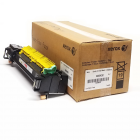
For Phaser® 7800:
115R00073 – 110 Volt version (Alternate #: 676K12630)
115R00074 – 220 Volt version (Alternate #: 676K12640)
REBUILD PROCEDURE (Part 1 of 2):
Tools Needed:
- Safety Torx T-15 Driver (Safety Torx drivers are the kind with the hole in the center of the driver bit… not everyone has one of these handy… there are five of this type of screws holding the Outer & Inner Covers in place. These are high-domed screws, so if you’re stuck and you don’t have a Safety T-15 driver, you could use needle-nose pliars to work them off one turn at a time (time consuming, but doable).
- Phillips Head #2 Screwdriver (also a 5.5mm hex driver is helpful)
- Small Flat-Head Screw Driver
Orientation:
Let’s start by getting oriented (refer to Photo #1). The “Rear” end is the end with most of the gears and the main fuser connector which interfaces with the machine. You’ll also find the CRUM Reset Fuse Board tucked into the rear end. The “Outer Face” is the face which is visible when you open the machine’s left door to go remove the fuser… it has a bunch of warning labels on it and the two thumb screws for removing the fuser are found on the bottom edge of this Outer Face. The “Top” of the fuser is where the yellow Fuser Exit Gate can be found. Now let’s strip this baby down.

1. Remove the “Outer Cover” (3 Safety-Torx T15 screws from the outer face). The yellow Exit Gate pivots on the top of this “Outer Cover”. If you wish to remove the Exit Gate, it is held captive by a small black plastic pin which holds the front-most pivot point. If you slide the plastic pin out of place with your thumb, the gate can come off (see Photo #2)

2. Remove the “Inner Cover” (2 Safety-Torx T15 screws from the inner face). (See photo #3 & #4).

3. Release the “Outer Frame”. This is a long metal piece with an attached black plastic channel on which the Fuser Exit Actuator hangs (2 Phillips head screws from the outer face). Disconnect the electrical connector at the rear end of the long blue wiring harness (see Photo #5). Then pivot the channel and metal piece away from the rear end (it is still connected at this point at the front end of the fuser)

4. Next you’ll want to remove the Front Wiring Guide (black plastic). (refer to Photo #6) First Disconnect the Fuser Exit Sensor’s bracket (1 screw) and then disconnect the white plug from the Fuser Motion Sensor which watches the fuser turning (this optical interrupt sensor watches the edge of a wheel with a series of flags on it). Shift the Front Wiring Guide (black plastic) towards the outer face till it clears the metal frame (to the right in the photo). Next fish the white plug near the middle of the black plastic piece out of its fastening hooks so that you can disconnect the white wire which disappears into the front end of the Fuser Heat Belt.

5. Remove the Pressure Roller Tie-Bar (2 Phillips head screws) and the Paper Input Guide (also held by 2 Phillips head screws). (see Photo #7 for a close-up of which screws you’ll be removing near the rear end). There is a static dissipating resistor mounted under the Paper Input Guide.

6. Remove the small black bracket which holds the Fuser CRUM Board from the rear end (1 screw). The little square Fuser CRUM board is tucked deep into the rear frame of the fuser. It has a 20 mA fuse and an indexing resistor. It is necessary to replace the fuse so that the fuser count will reset when you install the rebuilt fuser. The fuse must be soldered on.
7. Release the large Main Fuser Connector which is near the rear end (2 spring loaded shoulder screws)
8. Release the Rear Wire Guide (black plastic) which holds many of the wiring harnesses (1 screw near the center of it (see Photo #8), then pivot the far rear portion towards the “inner face” and off). Be patient… you will need to remove some of the wiring from its channels to get this piece far enough out of your way. For reassembly, refer to Photo #___ to see where the wiring is supposed to go.

9. Remove the Pressure Cam Shaft’s Home Sensor Actuator (1 screw) (see Photo #9). Next remove the Pressure Cam Shaft Assembly by removing the e-clip at the front end and a second e-clip just behind the metal frame piece at the rear end (between the Rear Cam and the Cam Shaft Home Sensor Actuator Flag). (see Photo # 9). You’ll need to slide the Cam Shaft to the rear, far enough for the front end of the shaft to clear the front metal frame and lift the front end up and… Then it will slide toward the front until the shaft clears its drive gear. Watch out not to lose any small pieces. The front and rear bearings will fall right off, as will the Cam Shaft Drive Gear and a plastic bushing found in the frame near the drive gear. Notes for reassembling the Pressure Cam Shaft Assembly: the Cams and the Home Sensor Actuator Flag line up with their rounded parts facing the same way. The 2 bearings have their flanges positioned outside of the metal frame on both ends. When reassembling, you will need to place the Drive Gear in its place and slide the “D-shaft” in to meet it.

10. Remove 2 shoulder screws from the front end (red screws as shown in Photo #10).

11. Now you can remove the Rear Metal Bracket Assembly (5 screws as shown in Photo #11). One of the screws (#4) is partly hidden behind part of the bracket. Since you can not get at it straight-on, the 5.5mm nut driver won't get it loose easily. You'll need a phillips head driver at an angle for that one. Be careful not to let any of the gears fall off, as several will be loose on their shafts at this point.

12. Next remove 1 more screw to take off a small metal plate which retains the largest black gear. Also remove 1 e-clip which holds the smaller black Press Roll Idler Gear (see Photo #12)

13. Remove the e-clips from the front & rear pressure pivot point shafts (see Photo #13 which shows the rear one)

14. Remove the Rear Inner Frame (2 red shoulder screws). See Photo #14 which shows the fully disassembled rear end.

15. Now you will remove the Pressure Roll Assembly. Gently lift the rear end of the Pressure Roll Assembly and then shift the assembly toward the rear end till it slides off of the Front Pivot Point Shaft. See Photo #15 which shows the Pressure Roll Assembly removed.

16. Moving on to the final stretch, remove the Heat Belt Stripper Plate (black plastic). You will want to first find something you can use as a gauge for spacing the Stripper Plate from the Heat Belt when you go to reassemble the fuser. A pair of flat creditcards serve well for this purpose (see Photo #16).

17. Remove the Heat Belt Assembly from its frame (4 screws, 2 from either end) Note that these 4 screws are short dome-headed Philips head screws. Be sure to re-use these same short screws in their right places during reassembly.
18. Carefully slide the old Heat Belt off of the Thermal Control Assembly, which is at its core. (see Photo #17)

19. Replace the Fuser Heat Belt Slip Sheet (7525FHBSS) and oil it well with the Heat Belt Oil… work the oil into the top and bottom of the fabric thoroughly. When sliding the new heat belt (7525FHB) back on, use an index card or business card to help sneak the belt past the edge of the slip sheet so it does not get “dog-eared”. Also be gentle with the Thermistor Heads. They stick out a bit, so you’ll need to tuck those thermistor heads back in as you slip the heat belt past them.
20. Reassemble everything... take your time. There are a lot of parts and a lot of screws, but with the photos in this write-up, and showing off your good mechanic skills, it'll all go back together nicely.

Well done... you've rebuilt a costly fuser and kept it from the landfills.
You can get the Fuser Rebuild Kits from us (7525FRK or 7800FRK). These are proving to be truly excellent quality parts throughout. We tried a few products before settling on the ones we carry. Longevity was the most important factor in our decision. The kit includes the Heat Belt, the Pressure Roll, the Slip Sheet, a small vial of Heat Belt Oil, and a Fuser Reset Fuse. |