Important: The information presented here is for the use of a qualified, experienced technician. Without the background knowledge which comes with training, you risk doing more damage then good to the copier & also risk your own safety. If you are not willing to take 100% responsibility for your actions, do not use the information posted here. Thank you. Read our conditions of Use for more information.
C35 Style - Drum Cartridge Rebuild Instructions
Xerographic Module (Drum Cartridge) Rebuild Instructions for all versions of the C35 Style copiers (for 113R00608, 113R00608, 113R00672, 113R00674, etc)
| Technical Specifications |
|---|
XEROGRAPHIC MODULE RECONDITIONING (Drum Cartridge Rebuilding for the C35 style):
For (DocumentCentre) DC535/545/555, (CopyCentre) C35/45/55, (WorkCentre) M35/45/55, Pro35/45/55, 113R608 (U.S. or Europe Type ‘B’ version) (Yield = 200,000) 113R610 (U.S. Type ‘A’ version) (Yield = 200,000) 113R607 (Europe Type ‘A’ version) (Yield = 200,000) For (BookMark) BK40/55, (CopyCentre) C165/175, (WorkCentre) WC-165/175, WC-245/255/265/275, Pro245/255/265/275, WC-5150, WC-5645/5655/5665/5687, WC-5745/5755/5765/5775/5790, wc-5845/5855/5865/5875/5890 113R672 (U.S. Type ‘B’ version) (Yield = 400,000) 113R674 (U.S. Type ‘A’ version) (Yield = 400,000) 113R673 (Europe “Sold” version) (Yield = 400,000)
The Xerographic Module is designed to have an estimated yield of 200K on some models and 400K on many of the newest models… this means the drum itself is made of some pretty good stuff and the 113R608 / 113R610’s drum will undoubtedly be capable of running a second cycle. You’ll want to be prepared to service the unit to repair drum cleaning problems and other issues which may arise during the life of the cartridge. Think of the Xerographic Module as just another part of the machine which requires regular service and you won’t miss out on that part of the action.
This write up is based on the 113R610 (Type ‘A’) and 113R608 (Type ‘B’). Some of the faster and newer models use a slightly different cartridge which added a self cleaning charge corotron shuttle. The repair procedure will be extremely similar, and the basic replacement parts are interchangeable (drum, & blade), but the cartridges do have some substantial differences which go beyond just the Connector CRUM (Customer Replaceable Unit Monitory) chip.
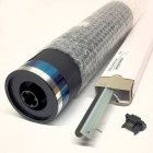
These cartridges come with a Transfer / Detack Corona Assembly in the box as well. The machines which are still set up for the “Metered” plan are ones which were sold with a Field Service Maintenance Agreement (FSMA)… the cartridges are included with the deal while they are under that maintenance agreement. The first time that a “Sold” version of the Drum Cartridge is installed in a “metered” plan machine, the machine changes to the “Sold” plan and will need to get the 113R610 ‘Sold’ (Type ‘A’) version of the cartridge from then on or else the Status Code “09-399” “Incompatible Xerographic Module” will show up. That Status Code will also appear if you try to install a cartridge from a different market. For example a European cartridge (113R607) would also result in a Status Code. The key to all of these market differences is held in the small Connector on the rear of the cartridge… the “CRUM” (Customer Replaceable Unit Monitor) which is programmed differently for each market. You’ll need a replacement Connector CRUM to reset the drum count. (see p.F-8) These cartridges are pretty straight forward with the exception of a trick being necessary to remove the Drum Hubs… 1.) You’ll want to remove the Top Cover first (4 screws from the top) then clean out whatever waste toner is easily reached from there. 2.) Next lay the unit on its Right Side… the drum will not be in danger of touching your work surface if the cartridge is in this position so you’ll want to keep it sitting like this for most of the balance of this procedure. Remove the Front Cover (1 screw from the front near the bottom… 5.5mm nut driver) 3.) Take notice of where the spring for the Stripper Finger Bracket attaches. Slide the Finger Bracket forward until the rear pin comes clear of the rear frame and remove the Finger Bracket and its spring. You will want to take care not to scratch the drum’s surface with the fingers (it might be wise to slide a piece of paper between the fingers and the drum before you slide the finger Bracket over). 4.) Here’s the tricky part… the Drum Hubs. We’ll start with the Rear Hub. Get a pair of pliers and get a firm grip on the rear hub and rotate the hub about ¼” counterclockwise… it will resist and then suddenly “pop” into a new position. Then it can be extracted. The hubs each have a pair of hooks with wedge shaped tips (one at the top, one at the bottom). The hooks prevent the hubs from being able to slide out unless they are turned to the removal position where there is clearance for the hooks. The wedge shapes at the tips of the hooks are indexed into a hole in the cartridge’s frame such that you need substantial force to rotate the hub into the removal position. … The author broke one trying to figure this out. The Front Hub works much the same way (except that you rotate the hub clockwise). When you remove the second hub, make sure the drum doesn’t drop out on you as it is only lightly retained when the hubs are out. The drum will now be removable from its cradle.
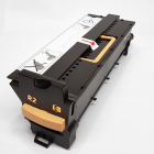
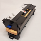
5.) The Cleaning Blade can be removed now (2 screws … 5.5 mm Nut Driver needed). Be very gentle with the mylar seal blade below the cleaning blade… if it gets damaged, the cartridge will likely drop sprinkles of toner into the paper path when you reinstall it. 6.) To remove the Charge Corona Assembly, pry the indented portion of the spring metal holding clips (one on the front end, and one on the rear) till you can slide the clip out away from the cartridge’s frame to release the Corona Assembly. 7.) Clean everything up really good… Reassemble the unit. Pay attention to the position of the large toothed mylar piece attached to the top cover… its teeth need to slide all the way down into the waste toner auger (it prevents the auger from clogging up). It is possible to position it against the drum instead which would obviously be bad news. 8.) Replace the Connector CRUM to reset the drum count. That should do the trick. |
| Information Reference |
Author: Britt Horvat, with special thanks to Kurt for his expertise and thanks also for support from whole Partsdrop gang. Originally published as an Article in the marvelous ENX Magazine - www.enxmag.com :) All rights reserved... you can distribute copies as long as you include a link to the source website: www.partsdrop.com |


Related Products