Important: The information presented here is for the use of a qualified, experienced technician. Without the background knowledge which comes with training, you risk doing more damage then good to the copier & also risk your own safety. If you are not willing to take 100% responsibility for your actions, do not use the information posted here. Thank you. Read our conditions of Use for more information.
7120 style - Fuser Rebuild Instructions
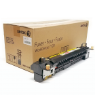
Fuser Module Repair and Rebuilding Instructions for the WC-7120, 7125, 7220, 7225
| Technical Specifications |
|---|
For Xerox® models: (WorkCentre) 7120, 7120T, 7125, 7125T, 7220, 7220T, 7225, 7225T
The WorkCentre 7120 series is a group of full color pure-breed Xerox machines which are worthy of our attention. These fellows share a lot of the basic design hallmarks of the 7425 style although they land on a slightly lower pricing level. As is usually the case, the fuser module is an important component which is pricy enough to warrant rebuilding. This fuser is slightly simpler than the 7425 fusers we covered in the past two articles… I think we can tackle this one in one article.
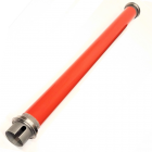
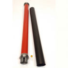
The 7120 fuser look very similar to the 7425 style fuser at first glance, and the basic design is pretty close, at least in concept. If you’ve read the 7425 fuser rebuild articles, this procedure will look familiar. In spite of the similar design however, the components don’t cross over for the most part. For example, the Fuser Heat Roller is considerably shorter on the 7120.
The WorkCentre 7120 and 7125 were released first, and they are joined now by the newer WC-7220 and 7225 models. The fuser module which fits all 4 models, is sold under the part number 008R13087 for the 110 volt version (overseas the 220 volt version is 008R13088). It has a stated yield of 80K according to some online sources although the OEM brochure doesn’t say. Pricing online ranges between $350.- and $500.-. The Fuser Heat Roller isn’t spared in the OEM Parts Book… but thankfully some good compatible Fuser Heat Rollers have recently surfaced which make this fuser rebuildable.
Lets get start by getting oriented… check out photo #1. The “Rear End” is the end with the Heat Roll Drive Gear and the main Fuser Connector. The “Outer Face” is the side which would face you if you were to walk up to the machine to remove the fuser and the “Inner Face” is the opposite side. The “Top” is where you’ll find the yellow Fuser Exit Guide.
Now let’s get right down to it:
PROCEDURE:
1.) First remove the “Outer Cover” (2 screws - 5.5 mm nut driver or #1 Philips Head)… the screw near the front end also retains a small square cover (take that off now because it will fall off easily). Swing the yellow exit guide all the way open. As you jiggle the Outer Cover off, be gentle at the Rear End, because there are wires going to the Fuser Exit Sensor which is mounted on the Outer Cover (see Photo #2)… You will need to raise the rear end off and disconnect the connector from that sensor.
2.) Remove the small rear end cover which also faces the “Outer Face” (1 screw). 3.) Next flip the module over and take off the “Inner Cover” (3 screws - refer to photo #3). Watch out… near the front end, there is a small Tensioner Arm which serves as a catch for the yellow exit guide. This piece can fall right off of the Inner Cover at this point. (see photo #4)
Now you can see the Thermistor / Thermostat Assembly which is beneath the Inner Cover. 4.) Release the front Thermostat (2 screws - #1 Phillips-Head) and pull the Fuser Heat Lamp terminal from the spade lug on the Thermostat (refer to Photo #5).
5.) Mark the position of the Heat Roll Stripper Guide (black plastic). You can mark it using a pen or marker on the metal frame (see Photo #6)… The idea is to make it easy to put the part back in the same place later when you go to reassemble everything (if this stripper is riding on the heat roll it will damage it and if it’s too far away, paper jams will result.
NOTE: Steps 6 through 9 will help clear a little bit of room for the Heat Lamp to shift towards the rear end of the fuser about 3 mm which is just enough to free up the lamp’s wires from the metal frame at the front end. 6.) Release the “Connector Holder Frame” which is a small metal frame on the rear end which holds the Main Fuser Connector (2 screws… marked “A1” & “A2” on Photo #7). Once that is released, you can remove the Fuser CRUM Board (that has a single 30mA pico-fuse on it for resetting the fuser counter).
7.) Next release the black plastic wire guide which is found just below the Connector Holder Frame if you look at Photo #7 (1 screw marked “B”). 8.) Also release the Rear Lamp Holder Frame (1 screw… found approximately where the arrow marked “C” is pointing on Photo #7). This piece secures the lamp’s rear ceramic end. 9.) Finally remove the Exit Idler Gear Bracket (2 screws… marked “D1” & “D2” on Photo #7). 10.) Release the Thermistor / Thermostat Assembly (5 screws - #1 Phillips) and move it so that you can shift the Heat Lamp towards the rear just far enough that the 2 front blue wires from the lamp will clear the metal frame (see Photo #8).
11.) Take note of how far the Fuser Pressure Screws protrude down below the frame (count threads or mark them so when you reassemble later, you can return the pressure back to where it was. (The example fuser which I used to produce this article had 6 threads showing below the frame on both ends). Then back out both Pressure Screws and hinge the Pressure Sleeve Assembly up and off of its hinge pins. 12.) Now the Fuser Heat Roll Assembly can be lifted out of its cradle. Slide it off of the “Front” end of the Heat Lamp (see Photo #9).
13.) Re-use the existing Heat Roll Bearings… these can be very stubborn… both coming off of the old roller and going onto the new one. You will need to use large mouth pliars or a similar tool and a hammer to tap the old bearings off (See Photo #10)
That should do the trick! |
| Information Reference |
Author: Britt Horvat, with special thanks to Kurt for his expertise and thanks also for support from whole Partsdrop gang. Originally published as an Article in the marvelous ENX Magazine - www.enxmag.com :) All rights reserved... you can distribute copies as long as you include a link to the source website: www.partsdrop.com |


Related Products