Important: The information presented here is for the use of a qualified, experienced technician. Without the background knowledge which comes with training, you risk doing more damage then good to the copier & also risk your own safety. If you are not willing to take 100% responsibility for your actions, do not use the information posted here. Thank you. Read our conditions of Use for more information.
DC250 style - DocuColor 250 Technical Information
DocuColor 250 (DC250 style)… Technical Information -
Xerox Docucolor 240, 250, 242, 252, 260, WorkCentre 7655, 7665, 7675, 7755, 7765, 7775, DCP700, 550/560/570, J75/C75
| Technical Specifications | |||||||||||||||||||||||||||||||||||||||||||||||||||||||||||||||||||||||||||||||||||||||||||||||||||||||||||||||||||||||||||||||||||||||||||||||||||||||||||||||||||||||||||||||||||||||||||||||||||||||||||||||||||||||||||||||||||||||||||||||||||||||||||||||||||||||||||||||||||||||||||||||||||||||||||||||||||||||||||||||||||||||||||||||||||||||||||||||||||||||||||||||||||||||||||||||||||||||||||||||||||||||||||||||||||||||||||||||||||||||||||||||||||||||||||||||||||||||||||||||||||||||||||||||||||||||||||||||||||||||||||||||||||||||||||||||
|---|---|---|---|---|---|---|---|---|---|---|---|---|---|---|---|---|---|---|---|---|---|---|---|---|---|---|---|---|---|---|---|---|---|---|---|---|---|---|---|---|---|---|---|---|---|---|---|---|---|---|---|---|---|---|---|---|---|---|---|---|---|---|---|---|---|---|---|---|---|---|---|---|---|---|---|---|---|---|---|---|---|---|---|---|---|---|---|---|---|---|---|---|---|---|---|---|---|---|---|---|---|---|---|---|---|---|---|---|---|---|---|---|---|---|---|---|---|---|---|---|---|---|---|---|---|---|---|---|---|---|---|---|---|---|---|---|---|---|---|---|---|---|---|---|---|---|---|---|---|---|---|---|---|---|---|---|---|---|---|---|---|---|---|---|---|---|---|---|---|---|---|---|---|---|---|---|---|---|---|---|---|---|---|---|---|---|---|---|---|---|---|---|---|---|---|---|---|---|---|---|---|---|---|---|---|---|---|---|---|---|---|---|---|---|---|---|---|---|---|---|---|---|---|---|---|---|---|---|---|---|---|---|---|---|---|---|---|---|---|---|---|---|---|---|---|---|---|---|---|---|---|---|---|---|---|---|---|---|---|---|---|---|---|---|---|---|---|---|---|---|---|---|---|---|---|---|---|---|---|---|---|---|---|---|---|---|---|---|---|---|---|---|---|---|---|---|---|---|---|---|---|---|---|---|---|---|---|---|---|---|---|---|---|---|---|---|---|---|---|---|---|---|---|---|---|---|---|---|---|---|---|---|---|---|---|---|---|---|---|---|---|---|---|---|---|---|---|---|---|---|---|---|---|---|---|---|---|---|---|---|---|---|---|---|---|---|---|---|---|---|---|---|---|---|---|---|---|---|---|---|---|---|---|---|---|---|---|---|---|---|---|---|---|---|---|---|---|---|---|---|---|---|---|---|---|---|---|---|---|---|---|---|---|---|---|---|---|---|---|---|---|---|---|---|---|---|---|---|---|---|---|---|---|---|---|---|---|---|---|---|---|---|---|---|---|---|---|---|---|---|---|---|---|---|---|---|---|---|---|---|---|---|---|---|---|---|---|---|---|---|---|---|---|---|---|---|---|---|---|---|---|---|---|---|---|---|---|---|---|---|---|---|---|---|---|---|---|---|---|---|---|---|---|---|---|---|---|---|---|---|---|---|---|---|---|---|---|---|---|---|---|---|---|---|---|---|---|---|---|---|---|---|---|---|---|---|---|---|---|---|---|---|---|
DocuColor 250 (DC250 style)… Technical Information - Xerox Docucolor 240, 250, 242, 252, 260, WorkCentre 7655, 7665, 7675, 7755, 7765, 7775, DCP700, 550/560/570, J75/C75
Warning : The diagnostics on these machines are designed to be used by experienced copier technicians only. These are very sensitive machines and changing the wrong NVM setting can potentially cause serious problems. Only use the information which follows if you are willing to take 100% responsibility for your actions.
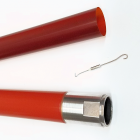
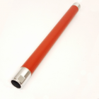
When we dove into the fuser modules for this same series a while back… I had noted that “few Xerox models have earned as much praise as the DocuColor 250 series”. I’ve not changed my mind on that. A good sign that this series is here to stay for a while is that there are new models just coming out that use the same engine (the WC 7755/7765/7775 were 2010 releases & J75/C75 models came out in 2014). These are all sturdy, full color machines with very few inherent problems to report. The machine is well laid out, and extremely technician friendly. Let’s get started with a brief introduction and then take a dip in the rather large pool of possible Fault Codes you might encounter. We’ll also cover how to get into the Diagnostic Mode so you can do things like testing components & clearing a few of the Faults which you may run into in your adventures.
Ok… I am told these machines are easy to work on as far as physical mechanics are concerned. How easy? Well there are 3 maintenance drawers. One with the Drum Cartridges and Developer units, a second one with the Transfer Belt Assembly and Belt Cleaner Assembly, and a third drawer with the 2nd BTR (Transfer Roll Assembly) and Fuser Module. A novice can take the DV Unit out if it came down to it. This is unusual and extremely refreshing. An engineering marvel by all means.
The various groups (or let’s call them “families”) of machines within this “DC250 style”, have many similarities but naturally there are differences as well. They share very similar fuser modules, toner cartridges and drum cartridges, so internally they are very similar… read near the end of this write up about the differences between models. The diagnostics are also very similar from family to family, except that the method to enter the diagnostic mode changed early on in the WC-7655 group of models (v2 software). We’ll cover the two ways to get into diagnostics after the fault code list.
The Fault Codes and their “RAPs” (Repair Analysis Procedures) in the Service Manual take up a whopping 900 + pages… so this list will have to be severely abbreviated. The plan is to stick to the codes which are more important to field techs. The codes are all laid out as 3 digits (the “Chain”) followed by a dash and then 3 more digits (the “Function”) (example: for ‘010-330’… the chain would be ‘010’). The first three digits do give some hint as to which part of the machine is being referred to (chain ‘010’ for example refers to fuser problems) … so it makes sense to generalize in the list as to what part of the machine the various “Chains” point to. Here goes:
FAULT CODE LIST:
Clearing some fault codes (from Diagnostics): Remember to always solve the cause of the fault before resetting them in memory. *Fuser Heat Control problems (010-319)… Read below about how to reset NVM value 744-351 back to ‘0’. **Fuser Overheat problems (010-320)… Read below about how to reset NVM value 744-350 back to ‘0’. ***Fuser NVM (memory) failure (010-324)… Read below about how to reset NVM value 744-352 back to ‘0’. ****IBT Belt Home Position Sensor Failure (042-326)… Read below about how to reset NVM value 741-105 to ‘0’ ***** Toner Dispense Problems... Read below about how to reset the appropriate NVM value. Fault 093-314 (393-314) for Yellow resets with 762-312 Fault 093-315 (393-315) for Magenta reset with 762-313 Fault 093-316 (393-316) for Cyan resets with 762-314 Fault 093-317 (393-317) for Black resets with 762-315
Warning : The diagnostics on these machines are designed to be used by experienced copier technicians only. These are very sensitive machines and changing the wrong NVM setting can potentially cause serious problems. Only use the information which follows if you are willing to take 100% responsibility for your actions.
1. Diagnostic Entry: For DC240/242/250/252/260: Hold down the ‘0’ button for 5 full seconds and then while still holding the ‘0’, press ‘Start’. A prompt for a password will show up (the “CE Access Number”). Use the default password ‘6789’, and press ‘Confirm’. 2. Press the “Log-in / Log-out” button… then on the touchscreen, touch “System Settings”, followed by “Common Settings”, and finally “Maintenance / Diagnostics”. 3. Choose “Dc131 NVM Read / Write”. 4. Touch the first empty block to enter the “chain” 744. The 1st three digits in an NVM code are called the “chain” and the second set of 3 digits are called the “Function”. Enter the appropriate “Function” code (351 for Fault Code 010-319, 156 for Fault Code 010-320, or 352 for Fault Code 010-324). Touch the “Read” button. The current setting will show up. Press “Val” to then change the value back to ‘0’ and press ‘Save’. 5. Finally when you exit diagnostics be sure to reboot the machine so the changes stick. Use the “Call Close” button.
The “Machine Status” Button: The “Machine Status” button near the lower left of the control panel gives folks access to the following stuff:
While the current fault code or message is normally displayed on the upper left corner of the screen, you may want to also view a Fault History Report to see what faults have been going on lately. This can be done by pressing the “Machine Status” button. Then touch the “Faults” tab. A button will show up which will allow you to print out the “Fault History Report”…
System Administrator Mode from the UI / Control Console: This password protected mode allows the key operator or administrator more access to things like default settings. If the default Usernames / Passwords do not work, you’ll need to ask the customer for the new password. For DC240/242/250/252/260: Press “Log-in/out” and enter the “Username” (the default username is ‘11111’ (five 1’s), then enter the “Password” (the default Password is ‘admin’). For 550/560/570, WC-7655/7665/7675, WC-7755/7765/7775, J75/C75: Press “Log-in/out” and If prompted for a Username, enter the default Username: ‘admin’… then enter the Password (the default is ‘1111’ (four 1’s)). For DCP700: Press “Log-in/out” and enter the Username “11111’, followed by the Password (Default = ‘x-admin’)
Once you’re in the System Administrator mode, you’ll see a menu with 4 choices:
System Settings brings you to a submenu: Common Settings, Copy Mode Settings, Scan Mode Settings, & Network Controller Settings.
If you choose “Common Settings” you’ll see a nice long list of choices:
DIAGNOSTICS UI (User Interface) Diagnostic Mode (also called “CE Mode”): CAUTION: I think it is very important to caution anyone who might read this, that the UI Diagnostic Mode is for experienced technicians … changing settings or running internal tests on these machines without an in-depth understanding of what you are doing can cause serious problems or even damage to the machine, and can also be dangerous for the person running the tests. Do not use the information presented here unless you are willing to take 100% responsibility for your actions. The process for getting into the UI Diagnostic Mode depends on exactly which model you’re working on. For DC240/242/250/252/260: Hold down the ‘0’ button for 5 full seconds and then, while still holding the ‘0’, press ‘Start’. A prompt for a password will show up (the “CE Access Number” screen). Use the default password ‘6789’ followed by ‘Confirm’. Next press the “Log-in / Log-out’ button.
Once you’re in UI Diagnostic Mode, choose ‘System Settings’, then choose ‘Common Settings’, followed by ‘Maintenance / Diagnostics’. Here you’ll find the most important menu… We’ll talk briefly about each of the menu items afterwards. Here are the things you’ll see:
This is a fair range of access. Don’t get me wrong… the authorized dealers who have the PWS Laptops (the Portable work Station) do maintain some significant advantages. The main limitation you face without a PWS (Portable Work Station), is that in “Component Control” and also in “NVM / Read Write” (memory settings), you can’t browse through a list of codes to choose from. For these two functions, you’ll need to know which code you are going to enter, so you’ll be needing lists of these codes. These lists are only viewable from the PWS’s screen.
Now lets have a more in-depth look at each of the menu choices from the list above:
Software Options: If you press “Software Options” followed by “Keyboard”, you can then punch in the password for the optional service you are installing or re-installing… then select ‘Save’ followed by ‘Reboot’.
Print Test Patterns: There are many available test patterns which are useful for troubleshooting copy quality problems and for isolating which board may be responsible for the symptom you are troubleshooting. There are a wide range of patterns to choose from…Each has its own 3 digit code. It appears that the list will not show up on-screen… so, you will need a list of the pattern’s 3 digit codes or else you’d be choosing blindly.
MAX Setup: The MAX setup menu contains the following stuff: • Procon ON/OFF Print • IIT Calibration • In/Out Manual Setup • ATC Sensor Setup • TRC Adjust • Tone Up/Down • Color Balance
Component Control: Here is where you’ll go to test Input Components such as Sensors and Switches… and also Output Components such as motors, solenoids, lamps, & clutches. You will be needing the list of codes and their corresponding components to use this at all since it does not appear in a menu on the Control Panel. We’ll cover the list in an abbreviated fashion in the next article. It is a very lengthy list.
Delete All Data: To quote the Service Manual: “This procedure deletes user-defined/registered information and information recorded automatically by the system from the hard disk, the ESS NVM PWB and Buffer RAM”. Do not do this unless you are sure what exactly will be deleted.
NVM Read / Write: This is covered later on in these pages… the lists of NVM codes are not browse-able from the Control Panel. The list is very long. See the list below starting on page 12… and be very careful with which settings you change. Keep a careful log and double check each code you are going to change to make sure it’s the right one.
Machine ID / Billing Data Settings There are 3 boards in the machine which all have the Serial Number, Product Number and Billing Counters: the MCU NVM PWB (the IOT or Main machine logic board), the SEEP ROM (on the ESS or Network Controller, known as Sys1), and the ESS NVM PWB (sys2 on the ESS or Network Controller). These 3 must agree with each other (otherwise a Fault Code will be called… 124-310, 124-311, 124-312, 124-313, 124-324, or 124-325). This process is designed to synchronize the three boards when one of them gets corrupted or needs to be replaced. From “Machine ID / Billing Data Settings”, choose a Board which has the correct data on it and select ‘Start’… Enter the correct Serial Number and then select ‘Confirm’.
Component Control Once you’re in UI Diagnostic Mode, choose ‘System Settings’, then choose ‘Common Settings’, followed by ‘Maintenance / Diagnostics’. Scroll down and choose “IO Check” & finally select: “Component Control”. From the Component Control screen, you’ll enter the “Chain” (the first 3 digits of the code) followed by the “Function” (the second 3 digits of the code). Press ‘Start’ to activate the test. For these Input Component Tests, you will be able to see on-screen the status of the component (H for high or L for low)… you can toggle the actuator or otherwise activate the switch or sensor you’re trying out and see if the status of the component changes on-screen. Press ‘Stop’ button to stop the current test. When you’re done, press ‘Close’ to leave the Component Control screen. Below is an abbreviated list of the component codes. There were simply too many codes to include. The ones which are missing were either relating to peripherals such as the finishers, or the description for the comoponent was too ambiguous to be of use. The list is followed by a quick run-down of what some of the acronyms stand for.
Input Component Codes:

Related Products
|