Important: The information presented here is for the use of a qualified, experienced technician. Without the background knowledge which comes with training, you risk doing more damage then good to the copier & also risk your own safety. If you are not willing to take 100% responsibility for your actions, do not use the information posted here. Thank you. Read our conditions of Use for more information.
7328 Family Tech Info Sheets
Technical Information for the WC-7328/7335/7345/7356 Model machines. Here are the basics of how to use the diagnostics to do things like resetting fault codes and setting up the ATC Sensor when installing new Developer Units... etc. Think of this as a distilled version of the service manual.
| Technical Specifications | ||||||||||||||||||||||||||||||||||||||||||||||||||||||||||||||||||||||||||||||||||||||||||||||||||||||||||||||||||||||||||||||||||||||||||||||||||||||||||||||||||||||||||||||||||||||||||||||||||||||||||||||||||||||||||||||||||||||||||||||||||||||||||||||||||||||||||||||||||||||||||||||||||||||||||||||||||||||||||||||||||||||||||||||||||||||||||||||
|---|---|---|---|---|---|---|---|---|---|---|---|---|---|---|---|---|---|---|---|---|---|---|---|---|---|---|---|---|---|---|---|---|---|---|---|---|---|---|---|---|---|---|---|---|---|---|---|---|---|---|---|---|---|---|---|---|---|---|---|---|---|---|---|---|---|---|---|---|---|---|---|---|---|---|---|---|---|---|---|---|---|---|---|---|---|---|---|---|---|---|---|---|---|---|---|---|---|---|---|---|---|---|---|---|---|---|---|---|---|---|---|---|---|---|---|---|---|---|---|---|---|---|---|---|---|---|---|---|---|---|---|---|---|---|---|---|---|---|---|---|---|---|---|---|---|---|---|---|---|---|---|---|---|---|---|---|---|---|---|---|---|---|---|---|---|---|---|---|---|---|---|---|---|---|---|---|---|---|---|---|---|---|---|---|---|---|---|---|---|---|---|---|---|---|---|---|---|---|---|---|---|---|---|---|---|---|---|---|---|---|---|---|---|---|---|---|---|---|---|---|---|---|---|---|---|---|---|---|---|---|---|---|---|---|---|---|---|---|---|---|---|---|---|---|---|---|---|---|---|---|---|---|---|---|---|---|---|---|---|---|---|---|---|---|---|---|---|---|---|---|---|---|---|---|---|---|---|---|---|---|---|---|---|---|---|---|---|---|---|---|---|---|---|---|---|---|---|---|---|---|---|---|---|---|---|---|---|---|---|---|---|---|---|---|---|---|---|---|---|---|---|---|---|---|---|---|---|---|---|---|---|---|---|---|---|---|---|---|---|---|---|---|---|---|---|---|---|---|---|---|
7328 family (WorkCentre®) 7228/7235/7245, 7328/7335/7345/7346* Tech Info Sheets
Finally there is a group of Xerox models which fall into the “C32 style” which technicians can repair without the fear of needing a “PWS” (Portable Work Station). The WorkCentre 7328, 7335, 7345, & 7346 Multifunction Copiers are refreshingly approachable. The predecessor models (C32, M24, DC1632, C2128, etc.) were plagued with problems relating to a lack of User Interface diagnostics. Not so for this most recent group, thank goodness. These are great machines… They’re well-built and capable of making some beautiful prints and copies. In this article, we’ll look into the more important parts & supply items and how to reset their counters. Then we’ll also look at how to get into the UI (User Interface) Diagnostics.
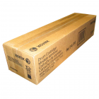
Drum Cartridges: Replacing the “Print Cartridge” (13R624) or the Connector CRUM (Customer Replaceable Unit Monitor) on the underside of the front end of the cartridge will reset the drum counter. The cartridges for the previous models are physically extremely similar however the CRUM being different makes them not interchangeable. Reconditioning these cartridges is possible thanks to the fact that they use the same Drum, Blade, & Charge Roll as the C32’s etc. which came before them.
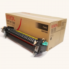
Fuser Modules (8R13040 / 8R13055): The fusers are considered to be Customer Replaceable Units. The models 7328, 7335, 7345 use fuser part# 8R13040, and 7346 uses a slightly different one (8R13055). They are capable of resetting the fuser counter automatically. If you want to repair a fuser, and you want the counter to reset automatically, you would need to replace 3 pico-fuses on a little board at the rear of the fuser module. (The 7346 version would require replacement of 1 pico-fuse). You can also choose to go into the Diagnostics and reset the HFSI counter for the fuser from there (read below about “Resetting Counters”).
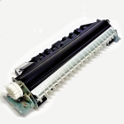
Transfer Roll Assembly (2nd BTR) (604K19991): The 7328 family uses the same Transfer Roll Assembly as the C2128/2636/3545 models used (the C32/DC1632 version would not fit on the 7328). The counter is reset similarly to the fuser module (read below).
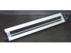
Transfer Belt Cleaner Assembly (IBT Cleaner) (604K07060 / 604K07061): This is another counter which can be reset from the diagnostics (read below). Keep in mind that the primary part which fails in the Cleaner Assembly is the IBT Cleaning Blade (C32IBTCB)… if the assembly is not otherwise broken, you can replace the blade and reset the counter and save some money over the cost of a complete assembly.
Entering Diagnostic mode (CE Diagnostic Mode):Hold ‘0’ for at least 10 seconds, then press ‘Start’… a password prompt should show up. Enter ‘6789’ followed by ‘Confirm’. Now press the ‘Machine Status’ button. You’ll see a set of Tabs as follows: - ‘Machine Information’ Tab: Serial Number, IP Address, and a convenient way to Print Reports the “Copy Report” which turns out to be 4 double-sided pages covering all of the machine’s features including the things having to do with Printing, Scanning, Network settings, etc.)
Choose ‘Tools’ and you will see 3 columns of choices… the one on the left will have 4 choices… choose the top one “System Settings”. The middle column has the heading “Group” and has a scrollable list. For “System Settings” you will see these choices: - ‘Common Service Settings’ This is the one we’ll be concentrating on.
From that middle column, choose ‘Common Service Settings’ to get to most of the good stuff. Under the right column (the heading which says ‘Features’) you will find yet another scrollable list of possibilities: - ‘Machine Clock / Timers’
There are other menu choices which may be worth exploring, however, most of the stuff us Techs would want are found by touching “System Settings”, followed by “Common Service Settings”, and then “Maintenance / Diagnostics”. Here you will find two pages of choices in the form of buttons. Among other choices, you will find: - Initialize Hard Disk - NVM Read / Write – Adjust memory settings & reset some fault conditions (read below under “Resetting some Fault Codes”). - IO Check - Access to Component Control for testing sensors, motors, etc. - Max Setup - Tools for setting up the color calibration & Registration. - Adjustment / Others: Reset Counters for things like the Transfer Roller or Belt Cleaner Assembly (read below under “Resetting Counters”).
Resetting Counters:For these models, you will need to get into the “UI Diagnostic Mode”: as explained above. Once you are in the Tools tab… choose the following from left to right: System Settings, Common Service Settings, and then in the right column, scroll down and touch “Maintenance / Diagnostics”. Scroll down and touch the button for “Adjustment / Others”. There you’ll find two choices: ‘Machine ID / Billing’ and ‘HFSI Counters’. Touch the ‘HFSI Counters’ button (High Frequency Service Items). Here you’ll be prompted to enter a “Chain-link” number… enter the appropriate number from this list: 1. 954-801 = IBT Belt (Transfer Belt) Then press ‘Confirm’ and some data shows up, including the current count on the part in question. If you then touch “Reset Current Value”… the machine will go to a confirmation screen where you need to touch ‘Reset’.
Resetting some Fault Codes:Some fault conditions will result in the machine locking-up until the fault is cleared by changing a memory setting back to ‘0’. This is true for Fuser Overheat faults, & Belt Home Position Failures. The machine locks up like this for good reason… it does not want to do any more damage to itself. Before you go and clear one of these faults, you must first make sure that whatever condition caused the fault in the first place has been repaired… otherwise the problem will happen again and probably right away. Enter “UI Diagnostics Mode” (read above), press the ‘Machine Status’ button followed by the ‘Tools’ Tab. Choose ‘System Settings’, ‘Common Service Settings’, and in the right column touch ‘Maintenance / Diagnostics’. From the menu of buttons which appear, choose “NVM Read / Write”. Enter the NVM (Non Volatile Memory) Chain-Link code from the list below for the fault code you want to reset. Touch the button which says “Confirm/Change”. The Current Value will show up in the “Current Value” field. Enter a ‘0’ in the ‘New Value’ Field and then press ‘Save’. This will write the new value to memory. .The next time the machine reboots, it will attempt to start up normally. Of course the source of the fault must be repaired first otherwise the fault condition will return. Resetting - Belt Home Position Failure Codes: 04-346 (or 09-350): First check the IBT Belt (transfer belt) to make sure it is not damaged and if you need to replace the belt, make sure that whatever damaged the belt in the first place is no lot going to destroy another belt. When you’re confident that the physical problem is repaired and solved, then follow the instructions above. Use Chain-Link ‘741-056’: Belt Home Failure”… Reset it to ‘0’. Resetting - Fuser Overheat codes: 10-348 or 10-350 If the code 10-348 or 10-350 come up even once, then the machine will lock up. Check for reasons for an over-heat condition. Replace or repair the Fuser Module and make sure the Fuser Cooling Fan isn’t all clogged up. Make sure there is adequate room around the machine to allow for good ventilation. To reset this one, you must enter diagnostic mode with the Front Door Interlock open. Reset Chain-Link code ‘744-003’ to “0’ if it shows a value of ‘1’ or ‘2’. Resetting ATC Sensor Faults (Automatic Toner Concentration): 09-380, 09-381, 09-382, 09-383, or 09-548 Check for trouble in toner dispensing or a loose ATC Sensor one is on each color developer unit. To reset the code, reset ‘Chain-link’ code ‘752-109 through 752-112’ back to ‘0’.
Component Control (Testing motors, sensors, etc.)Testing of various parts in the machine can be done from the ‘IO Check’ feature. Get into the “UI Diagnostics” as explained earlier… Press the ‘Machine Status’ button and choose the ‘Tools’ tab. Then choose ‘Common Service Settings’ & ‘Maintenance / Diagnostics’ and look for a button which says ‘IO Check’. Touching that button will bring up a screen with two choices: “Component Control” or “Analog Monitor”. If you touch ‘Component Control’, the screen will ask you for a ‘Chain – Link’ number. Unfortunately you need to know which code you want to enter for the appropriate component and the machine does not give you a scrollable list to choose from. You’ll need to get the Chain-Link codes. Maybe a future article in the making?
Toner Cartridges and related problems:Now let’s talk about the Toner Cartridges. The machines initially came with the original “Fuji” cartridge part numbers : 6R01280 (black), 6R01281 (yellow), 6R01282 (magenta), and 6R01283 (cyan). Then the cartridges folks buy here in the U.S. are 6R01175 (black), 6R01176 (yellow), 6R01177 (magenta), and 6R01178 (yellow). The two sets of ctgs are interchangeable with one another. New Toner Cartridges do not have a CRUM chip nor a fuse on them as you might expect. Instead they signal to the machine that they’re new cartridges using a physical actuator which pushes a switch. On the rear end of the cartridge, on top, you will see a metallic piece which changes positions when the toner dispense first kicks-in. As the coupling at the rear of the cartridge begins to turn, the metallic piece gets pushed away from the center, towards the top edge of the cartridge. This metallic piece is in position to push the “new cartridge switch” in the machine when it first slides in (the metal is visible in a square hole at the rear end of the cartridge), then after the metal piece gets pushed toward the outer edger of the cartridge, it leaves the square hole in the rear of the cartridge "open" so that if you tried to use the same cartridge to reset a second machine's toner cartridge count, it would not reset it. If you had a cartridge like that which was still full and you wanted to use it in a machine which was calling for toner, you'd need to slide the metal piece back in, to its original starting position closer to the center of the round of the cartridge... where it is visible and blocking the square hole again. If a new cartridge is installed and it fails to push the “new cartridge switch”, the machine goes into a fault code: 009-390 (for black), 009-391/392/393 (for Cyan/Magenta/Yellow) and must be reset manually from diagnostics. The Service Manual is a little vague and a tad-bit confusing on which NVM (Non Volatile Memory) codes need to be reset to clear the fault codes. In the procedure for these fault codes, they tell you that if the metallic actuator did not move out to the top edge of the cartridge, you should move it up by hand and then go and reset what they call the “Accumulative Dispense Time” back to “0”. Looking at the list of memory codes in the service manual (NVM Chain – Link codes), the ones mentioned in the procedure are not shown in the list. Instead there is another set of 4 codes which are named “Fail Dispense Unusual”. The description says the code means that when the toner dispense turned on with a new toner cartridge, it failed to shift from “new to old”. Try resetting both memory settings relating to the color you’re dealing with. See the list of codes below: To clear “New Toner Cartridge not Detected” fault codes: 009-390(K), 009-391(C), 009-392(M), 009-393(Y), reset the appropriate NVM (memory) location / locations back to “0”:
Toner Dispense problems have the potential to lead to deeper complications… especially if they were to go-on unchecked. For this reason, the machine will “lock up” if it sees that the developer in the DV Unit is starving for toner. An ATC (Automatic Toner Concentration) sensing fault will be called depending on which color is having trouble. You’ll want to troubleshoot the problem. Check to be sure the Toner Dispense Motor (drives the coupling at the rear end of the toner cartridge) is working and that nothing is clogged up preventing the toner from moving into the DV unit from the toner cartridge. A loss of developer material in the DV Unit (or contamination of the developer) can also cause ATC Sensor Failures. If you remove the drum cartridge, you can see the mag roller to make sure it’s not getting bald from lack of developer material. Once you’ve repaired the cause of the failure, you will need to reset the Fault Code by changing a memory (NVM) setting back to ‘0’. Below are the Fault Codes and the corresponding NVM (memory) locations for each color. ATC Sensor Failures – Fault Codes and Memory locations to reset:
This series uses a developer trickle system in which each new toner cartridge has a small bit of developer material mixed in with the toner. The older developer gets pushed out as the new material from the toner takes its place. The idea being that you’ll always have fresh developer in there. This makes it difficult to properly test any aftermarket toner refills or refilled cartridges because even if the compatible toner makes a glorious copy to begin with… if the developer which the manufacturer has mixed into the toner is not quite right, it’ll take 5-6 cartridges before the compatible developer replaces a majority of the original developer. If that new developer is “off” the copy quality will gradually fail. Now what happens if you have to replace a complete Developer Unit? DV units have a stated yield of approximately 650K. Be forewarned it’s a relatively big job to get one or more of the DV Units out of the machine. You have to get at them from the front end. This means removing panels, loosening up the metal front plate and removing the dispense assemblies. Once you grab a new Developer Unit, you’ll need to remove a reference tag from the label on the new unit’s ATC sensor. That tag has a 3 digit number on it. You’ll need the numbers off of the tag in order to calibrate the new ATC Sensor. If you thought that the physical replacement procedure was complicated, you’ll really cringe at how complicated the ATC Sensor calibration is. The 3 digit code can be found on the 3rd line of text on the label. The first digit will always be a ‘0’ . To calibrate the new ATC Sensor , first enter the Diagnostic Mode (Hold ‘0’ for at least 10 seconds, then press ‘Start’… a password prompt will show up. Enter ‘6789’ followed by ‘Confirm’. Then press the ‘Machine Status’ button). Choose the “Tools” tab and then “System Settings” followed by “Common Service Settings” and then choose “Maintenance / Diagnostics” followed by “Max Setup”. Finally you will touch the “ATC Sensor Setup” button. Select the boxes in columns 1 and 2 of the ATC Sensor Setup screen that are for the color you are dealing with (Y, M, C or K). Find your ATC Calibration Code (from the ATC Sensor’s tag mentioned earlier) on the chart below and enter the “Sensitivity Gradient Value” and the “Standard TC Output Default Value” in the empty fields. Press ‘Start’ to run the routine. When it’s done, touch the “Close” button and go ahead and exit diagnostics. The machine will reboot and the new settings will be stored.
ATC Sensor Calibration Chart:
Hopefully the information here will prove helpful to everyone.
|
||||||||||||||||||||||||||||||||||||||||||||||||||||||||||||||||||||||||||||||||||||||||||||||||||||||||||||||||||||||||||||||||||||||||||||||||||||||||||||||||||||||||||||||||||||||||||||||||||||||||||||||||||||||||||||||||||||||||||||||||||||||||||||||||||||||||||||||||||||||||||||||||||||||||||||||||||||||||||||||||||||||||||||||||||||||||||||||
| Information Reference | ||||||||||||||||||||||||||||||||||||||||||||||||||||||||||||||||||||||||||||||||||||||||||||||||||||||||||||||||||||||||||||||||||||||||||||||||||||||||||||||||||||||||||||||||||||||||||||||||||||||||||||||||||||||||||||||||||||||||||||||||||||||||||||||||||||||||||||||||||||||||||||||||||||||||||||||||||||||||||||||||||||||||||||||||||||||||||||||
| Originally published as an article in ENX Magazine: “WC-7328 family … A Breath of Fresh Air (PWS not required… no need to run)” |

Related Products